TEA1761T_2
?NXP B.V. 2007. All rights reserved.
Product data sheet
Rev. 02 25 April 2007
7 of 13
NXP Semiconductors
TEA1761T
GreenChip synchronous rectier controller
10. Characteristics
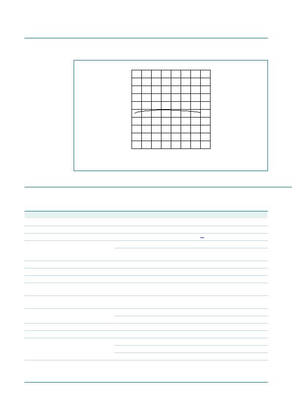
Fig 4. Typical regulated V
SENSE
voltage versus junction temperature
junction temperature (癈)
50
150
100
0
50
001aae779
2480
2520
2440
2600
regulated
VSENSE
voltage
(mV)
2400
Table 5.
Characteristics
T
amb
= 25 癈; V
CC
= 20 V; all voltages are measured with respect to ground (pin 2); currents are positive when owing into
the IC; unless otherwise specied.
Symbol
Parameter
Conditions
Min
Typ
Max
Unit
Supply voltage management (pin V
CC
)
V
startup
start-up voltage
8.35
8.6
8.85
V
V
hys
hysteresis voltage
[1]
0.5
V
I
CC(oper)
operating supply current V
CC
= 8 V (V
CC
< V
startup
)
-
1
-
mA
under normal operation; no load on
pin DRIVER
-
1.4
-
mA
Synchronous rectication sense input (pin SRSENSE)
V
act(drv)
driver activation voltage
340 310 280 mV
V
reg(drv)
driver regulation voltage
65
55
45
mV
V
deact(drv)
driver deactivation
voltage
12
mV
t
d(act)(drv)
driver activation delay
time
-
125
-
ns
t
act(sr)(min)
minimum synchronous
rectication active time
Short time
1.5
2
2.5
祍
Long time
1.7
2.2
2.7
祍
Driver (pin DRIVER)
I
source
source current
V
CC
= 15 V; voltage on pin DRIVER = 2 V
0.3
0.25 0.2
A
I
sink
sink current
V
CC
= 15 V;
voltage on pin DRIVER = 2 V
1
1.4
-
A
voltage on pin DRIVER = 9.5 V
2.2
2.7
-
A
V
o(max)
maximum output voltage V
CC
= 15 V
-
10
12
V
发布紧急采购,3分钟左右您将得到回复。
相关PDF资料
TEA1762T/N2/DG,118
IC CTLR SMPS SW SO14
TEA1791T/N1,118
IC CTRLR GREENCHIP SYNC 8-SOIC
TMP03FS-REEL
IC SENSOR TEMP/SERIAL OC 8SOIC
TMP141AIDBVTG4
IC TEMP SENSOR DGTL OUT SOT23-6
TMP401AIDGKTG4
IC TEMP SENSOR DGTL OUT 8-MSOP
TPS2346PWRG4
IC HOT SWAP POWER MGR 24-TSSOP
TPS24711DGSR
IC CTRLR HOT SWAP 2.5-18V 10MSOP
TPS2491DGSG4
IC POS HV HOT-SWAP CTRLR 10-MSOP
相关代理商/技术参数
TEA1761T/N2/DG
制造商:NXP Semiconductors 功能描述:SYNC REC CNTRL & FEEDBACK SO8 制造商:NXP Semiconductors 功能描述:SYNC REC CNTRL & FEEDBACK, SO8
TEA1761T/N2/DG,118
功能描述:DC/DC 开关控制器 2.7A 0.45W 10% RoHS:否 制造商:Texas Instruments 输入电压:6 V to 100 V 开关频率: 输出电压:1.215 V to 80 V 输出电流:3.5 A 输出端数量:1 最大工作温度:+ 125 C 安装风格: 封装 / 箱体:CPAK
TEA1761T/N2/DG118
制造商:Rochester Electronics LLC 功能描述: 制造商:NXP 功能描述: 制造商:NXP Semiconductors 功能描述:
TEA1762T
制造商:PHILIPS 制造商全称:NXP Semiconductors 功能描述:GreenChip synchronous rectifier controller
TEA1762T/N2,118
功能描述:DC/DC 开关控制器 SYN Rectifier Controller 14-Pin RoHS:否 制造商:Texas Instruments 输入电压:6 V to 100 V 开关频率: 输出电压:1.215 V to 80 V 输出电流:3.5 A 输出端数量:1 最大工作温度:+ 125 C 安装风格: 封装 / 箱体:CPAK
TEA1762T/N2/DG,118
功能描述:DC/DC 开关控制器 3.5V 5mA 10% RoHS:否 制造商:Texas Instruments 输入电压:6 V to 100 V 开关频率: 输出电压:1.215 V to 80 V 输出电流:3.5 A 输出端数量:1 最大工作温度:+ 125 C 安装风格: 封装 / 箱体:CPAK
TEA1771
制造商:PHILIPS 制造商全称:NXP Semiconductors 功能描述:GreenChip PC primary control IC
TEA1771T/N2,518
功能描述:DC/DC 开关控制器 TEA1771T/SO24/REEL13DP//N2 RoHS:否 制造商:Texas Instruments 输入电压:6 V to 100 V 开关频率: 输出电压:1.215 V to 80 V 输出电流:3.5 A 输出端数量:1 最大工作温度:+ 125 C 安装风格: 封装 / 箱体:CPAK
